
By The Roofing Brief Team | Last reviewed: November 2026
Roof valley framing means setting a valley rafter (or, in a California valley, a flat valley plate on the finished main roof) along the inside corner where two roof planes meet, then running jack rafters from each ridge down onto it. Under IRC R802.4.3 the valley rafter must be at least 2 in nominal thick, at least as deep as the cut end of the rafters framing into it, and braced at the ridge to a bearing partition or designed for that point load. On a 6:12 roof each foot of common run takes 18.00 in of valley rafter, and valley jacks step down 17-7/8 in at 16 in on center.
The numbers below are worked from the 2024 International Residential Code (IRC) text and plain trigonometry, checked against published framing references. The cross gable roof guide covers the roof style and its valley lengths by wing width; this page is the carpentry: sizing the valley, laying out the jacks, cutting them, and choosing between a conventional, supporting or California valley.
Key numbers at a glance
These six figures answer most roof valley framing questions on a stick-framed house. Each one is a code minimum or a geometry constant, so a local amendment, an engineer’s drawing or a truss design can override it but cannot make it smaller.
| Item | Number | Source |
|---|---|---|
| Minimum valley rafter thickness | 2 in nominal (one 2x member) | IRC R802.4.3 (2021 and 2024) |
| Minimum valley rafter depth | Not less than the cut end of the rafter | IRC R802.4.3 |
| Slope below which hips and valleys must be designed as beams | Under 3:12 (25 percent slope) | IRC R802.4.4 |
| Valley rafter length per foot of common run, 6:12 | 18.00 in (valley run 16.97 in per 12 in) | Geometry; matches framing-square hip/valley tables |
| Jack rafter length difference, 6:12 | 17-7/8 in at 16 in o.c.; 26-13/16 in at 24 in o.c. | Geometry; framing-square jack tables |
| Jack rafter to valley nailing | 4-16d box toenails, or 3-16d box end nails (or listed equivalents) | IRC Table R602.3(1), item 7 |
Hips and valleys on a roof: what is the difference?
On roof hips and valleys, a hip is the outside (convex) corner where two planes meet over an outside wall corner, and a valley is the inside (concave) corner where they meet over an inside corner. Vertex Engineering’s hip and valley primer, which draws on the American Wood Council’s Wood Frame Construction Manual (WFCM 2018), explains why the two behave differently: opposing hip jacks lean on each other, while valley jacks hang their load on the valley.
| Feature | Hip | Valley |
|---|---|---|
| Corner type | Outside corner, sheds water away | Inside corner, collects water from 2 planes |
| Jack rafters run | From wall plate up to the hip | From the ridge down to the valley |
| Structural behavior above 3:12 | Opposing jacks form truss action; hip acts mostly as a nailer when ties resist thrust (Vertex) | Jacks load it downward like a floor girder; Vertex advises treating it as a beam at every slope |
| Code minimum size | 2 in nominal, depth of rafter cut end (R802.4.3) | Same as hip (R802.4.3) |
| Top-edge treatment | Dropped or backed so sheathing clears the edges | Backed (V-groove) or jacks set to the centerline |
| Roofing detail | Hip cap shingles | Valley lining: 24 in metal or 36 in roll roofing minimum (IRC R905.2.8.2) |
The practical difference shows up in failures. Vertex reports a New England valley beam that cracked in half under snow in the winter of 2014 to 2015, and works an example in which a 10 ft by 10 ft tributary area at 30 psf ground snow needs (2)-2×10 per WFCM Table 3.28, where a single 2×6 would be undersized by almost a factor of five.
What the IRC requires for valley rafters
Four IRC sections control a stick-framed valley: R802.4.3 sets the minimum size and the ridge brace, R802.4.4 forces beam design under 3:12, R802.6 sets bearing, and Table R602.3(1) sets the nails. The wording below is the 2024 IRC as reproduced by UpCodes (2024 IRC chapter 8); the same R802.4.3 and R802.4.4 text appears in the 2021 IRC chapter 8 on ICC. Confirm the edition your building department enforces.
| Section | What the code text says | What it means at the valley |
|---|---|---|
| R802.4.3 Hips and valleys | “Not less than 2 inches (51 mm) nominal in thickness and not less in depth than the cut end of the rafter.” Supported at the ridge “by a brace to a bearing partition or be designed to carry and distribute the specific load at that point.” | A single 2x is the floor, not a sizing rule; the top end needs a brace or an engineered connection |
| R802.4.4 Rafter supports | Under 3:12, “ridges, hips and valleys, shall be designed as beams,” with bearing per R802.6 | Low-slope valleys always need a design |
| R802.6 Bearing | At least 1-1/2 in of bearing on wood or metal, 3 in on masonry or concrete | Applies to the valley foot at the wall plate and to jacks |
| Table R602.3(1), item 7 | Rafters to ridge, valley or hip: 4-16d box (3-1/2 x 0.135 in) toenails, or 3-16d box or 2-16d common end nails | Minimum jack-to-valley nailing |
| R802.10.4 Alterations to trusses | No cutting, notching, drilling or splicing without a registered design professional’s approval | A valley landing on a truss roof needs the truss designer’s detail |
| R803.2.2 Allowable spans | Panel roof sheathing spans per Table R503.2.1.1(1) or APA E30 | Valley sheathing edges need support from jacks or blocking within the panel’s span rating |
The fastener figures come from IRC Table R602.3(1) on UpCodes, which also lists roof sheathing of 3/8 to 1/2 in at 8d common (2-1/2 x 0.131 in) nails, 6 in on center at edges. Many jurisdictions in high-wind zones add hangers or straps on top of these minimums.
Supported, supporting and California valleys: the 4 framing methods
There are four ways to frame a valley, and the ridge heights decide which one applies. When both ridges sit at the same height, two equal valleys meet at the ridge. When the wing ridge is lower, Tim Uhler’s JLC article on framing a supporting valley (April 2015) runs one long supporting valley to the main ridge and frames the second, shorter supported valley into it at 90 degrees in plan.
| Method | How it works | Best fit | Watch for | Source |
|---|---|---|---|---|
| Conventional valley rafter | One valley rafter per inside corner, from the plate corner to the ridge; jacks from both ridges | Equal ridge heights | Brace at the ridge per R802.4.3 | IRC R802.4.3 |
| Supporting and supported valley | Long valley runs plate to main ridge and carries the lower ridge; short valley butts it at 90 degrees in plan | Lower wing ridge that cannot be posted | Uhler’s example used a double 1-3/4 in LVL and 5/8 in threaded rod with bearing plates at the intersection | JLC, Uhler 2015 |
| California (blind, overlay) valley | Main roof framed and sheathed first; valley plates nailed on top; jacks land on the plates | Additions, production framing, truss roofs | Jack loads land on main roof rafters or truss top chords | Fine Homebuilding, Haun 1993; Spier 2024 |
| Truss valley set | Factory valley trusses step down on top of the main trusses | All-truss roofs | Layout and bearing come from the truss design drawings (IRC R802.10.1) | IRC R802.10 |
How deep does a valley rafter need to be?
The valley rafter has to be at least as deep as the plumb cut on the jacks that frame into it, and that cut is taller than the jack stock: a 2×8 (7-1/4 in actual) cut plumb at 6:12 is 8.11 in tall. Uhler’s JLC valley shows the same effect with 2×12 commons at 6:12, which measure 12-9/16 in plumb. The table compares each jack’s plumb cut with the vertical face of a single valley rafter, which is also stretched because the valley slopes more gently than the roof.
| Jack or common rafter | Plumb cut at 4:12 | Plumb cut at 6:12 | Plumb cut at 8:12 | Plumb cut at 12:12 | Smallest single valley stock that covers it |
|---|---|---|---|---|---|
| 2×6 (5-1/2 in) | 5.80 in | 6.15 in | 6.61 in | 7.78 in | 2×8 at every pitch shown |
| 2×8 (7-1/4 in) | 7.64 in | 8.11 in | 8.71 in | 10.25 in | 2×10 at every pitch shown |
| 2×10 (9-1/4 in) | 9.75 in | 10.34 in | 11.12 in | 13.08 in | 2×12 at every pitch shown |
| 2×12 (11-1/4 in) | 11.86 in | 12.58 in | 13.52 in | 15.91 in | Deeper than any 2x: 14 in LVL or engineered member |
Roofing Brief calculation: plumb cut = rafter depth divided by the cosine of the roof angle (26.57 degrees at 6:12); a valley’s vertical face = its depth divided by the cosine of the valley angle (19.47 degrees at 6:12). The rule of thumb that falls out is “one nominal size deeper than the jacks.” That satisfies the minimum depth in R802.4.3 only; load sizing still comes from WFCM Table 3.28 or an engineer, and a doubled member is common once the valley carries snow or a supported valley.
Valley and jack rafter numbers by pitch
Every valley calculation runs on two unit lengths: the common rafter length per 12 in of run and the valley rafter length per 16.97 in of valley run (the 45 degree diagonal of 12 in by 12 in). The table adds the jack length step and the two adjustments for the valley’s top edge, the backing bevel and the vertical drop at each edge. These match the hip/valley and jack tables stamped on a steel framing square and the Swanson Speed Square Blue Book chapter on jack rafters.
| Pitch | Common rafter per ft of run | Valley rafter per ft of common run | Valley slope | Jack difference at 16 in o.c. | Jack difference at 24 in o.c. | Backing bevel | Edge drop, 1-1/2 in valley | Edge drop, 3 in valley |
|---|---|---|---|---|---|---|---|---|
| 4:12 | 12.65 in | 17.44 in | 2.83:12 | 16.87 in | 25.30 in | 12.9 deg | 0.18 in | 0.35 in |
| 5:12 | 13.00 in | 17.69 in | 3.54:12 | 17.33 in | 26.00 in | 15.8 deg | 0.22 in | 0.44 in |
| 6:12 | 13.42 in | 18.00 in | 4.24:12 | 17.89 in | 26.83 in | 18.4 deg | 0.27 in | 0.53 in |
| 7:12 | 13.89 in | 18.36 in | 4.95:12 | 18.52 in | 27.78 in | 20.9 deg | 0.31 in | 0.62 in |
| 8:12 | 14.42 in | 18.76 in | 5.66:12 | 19.23 in | 28.84 in | 23.1 deg | 0.35 in | 0.71 in |
| 9:12 | 15.00 in | 19.21 in | 6.36:12 | 20.00 in | 30.00 in | 25.1 deg | 0.40 in | 0.80 in |
| 10:12 | 15.62 in | 19.70 in | 7.07:12 | 20.83 in | 31.24 in | 26.9 deg | 0.44 in | 0.88 in |
| 12:12 | 16.97 in | 20.78 in | 8.49:12 | 22.63 in | 33.94 in | 30.0 deg | 0.53 in | 1.06 in |
Roofing Brief calculation for equal pitches meeting at 90 degrees. Valley rafter per foot = square root of (16.97 squared plus rise squared). Jack difference = spacing times common length per foot, divided by 12. Backing bevel = arctangent of (0.7071 times rise/12 times the cosine of the valley angle); the 18.4 degree result at 6:12 matches the backing bevel in Uhler’s JLC valley. Edge drop = half the valley thickness times rise divided by 16.97.
The valley slope column explains the leak math as well as the framing: at 4:12 the valley itself drains at only 2.83:12, below the 3:12 line, which is one reason the roof valley flashing guide calls for full self-adhering membrane in low-slope valleys.
Worked example: framing the valleys on a 6:12 T-wing
A 24 ft wide wing joins a 28 ft wide main house, both at 6:12, both with 1-1/2 in ridge boards, 2×8 rafters at 16 in on center and the same plate height. The wing ridge (6 ft above the plate) sits 1 ft below the main ridge (7 ft above the plate), so the framing follows the supporting and supported valley method. All lengths are theoretical centerline lengths before plumb and seat cuts.
| Member | Inputs | Arithmetic | Result |
|---|---|---|---|
| Wing common rafter | Run 12 ft minus half the 1-1/2 in ridge = 143.25 in | 143.25 x 13.416 / 12 | 160.16 in (13 ft 4-3/16 in) |
| Valley stock | 2×8 jacks, plumb cut 8.11 in at 6:12 | Smallest 2x with a vertical face over 8.11 in | 2×10 minimum depth; supporting valley doubled (3 in) |
| Supporting valley | Main common run 14 ft; deduct half the ridge at 45 degrees | 14 x 18.00 = 252 in, minus 0.75 x 1.414 x 1.061 = 1.13 in | 250.87 in (20 ft 10-7/8 in) |
| Supported valley | Wing common run 12 ft; butts a 3 in supporting valley | 12 x 18.00 = 216 in, minus 1.5 x 1.061 = 1.59 in | 214.41 in (17 ft 10-7/16 in) |
| Valley jack step | 16 in o.c. at 6:12 | 16 x 13.416 / 12 | 17.89 in (17-7/8 in) |
| Jack deductions | Half ridge at top, half of a 1-1/2 in valley at 45 degrees at bottom | 0.75 x 1.118 = 0.84 in; 0.75 x 1.414 x 1.118 = 1.19 in | 2.03 in off each theoretical jack |
| Backing bevel and drop | 3 in supporting valley at 6:12 | From the pitch table | 18.4 degree bevel, or 0.53 in edge drop |
The jack schedule then steps down in equal increments. The 8 jacks on one side of the supported valley, numbered from the ridge end, run 17.89, 35.78, 53.67, 71.55, 89.44, 107.33, 125.22 and 143.11 in theoretical, or 15-7/8, 33-3/4, 51-5/8, 69-1/2, 87-7/16, 105-5/16, 123-3/16 and 141-1/16 in after the 2.03 in deduction, measured on the centerline of the top edge. Cutting a long and a short jack from each board, as Swanson’s Blue Book describes, leaves the offcut with the opposite cheek already on it for the other side of the valley.
How to frame a roof valley, step by step
A conventional valley goes in after the ridges and the commons that hold them straight, and before the jacks. The sequence below follows Uhler’s assembly order in JLC (main ridge, supporting valley, supported valley, minor ridge, infill jacks) with the IRC checks added at each step.
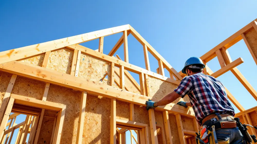
- Measure as built. Take the wing and main spans from the walls including sheathing, as Rick Arnold recommends in Fine Homebuilding’s guide to framing a roof valley, not from the plans. Halve each span and subtract half the ridge thickness to get the common run.
- Size the valley. Pick stock one size deeper than the jacks (2×10 for 2×8 jacks), then confirm load sizing with WFCM Table 3.28 or an engineer. Any valley under 3:12 must be designed as a beam (IRC R802.4.4).
- Snap the layout. Snap the ridge lines and the valley centerlines full scale on the ceiling joists or deck. On equal pitches each valley runs 45 degrees in plan from the inside wall corner.
- Cut the valley. Mark the top plumb cut with the valley ratio (6 on the tongue and 17 on the blade of the square for 6:12; 16.97 exact), cut a double 45 degree cheek where it meets the ridge, and cut the birdsmouth so the seat bears at least 1-1/2 in on the plate (IRC R802.6).
- Back or drop it. Plane an 18.4 degree backing bevel on each top edge at 6:12, or set the jacks so their tops align with the valley centerline, so sheathing lies flat across the V.
- Set and brace the valley. Nail the top to the ridge and brace it to a bearing partition, or install the designed post or hanger (IRC R802.4.3). Crown every member up.
- Cut the jacks. Mark a common plumb line on each jack and saw it at a 45 degree bevel along that line; per Swanson, that one cut gives the plumb and the cheek on equal pitches. Step lengths down by 17-7/8 in at 16 in o.c. (6:12).
- Nail the jacks in pairs. Fasten each jack to the valley with 4-16d box toenails or 3-16d box end nails (Table R602.3(1), item 7), or a listed connector, working opposite sides together so the valley stays straight.
- Add blocking for the sheathing. Block between jacks where a panel edge falls in the valley so no edge spans farther than its rating under Table R503.2.1.1(1).
- Sheath and dry in. Nail 3/8 to 1/2 in panels with 8d common nails at 6 in on edges, then line the valley before shingling.
For a listed connector at step 8, Simpson Strong-Tie’s LSSJ jack hanger is field-slopeable up to 12:12 and connects a jack to either a hip or a valley; Simpson says its partial seat meets the IRC R802.6 bearing requirement. Check the load table for your rafter size before substituting it for nails.
California valleys: framing one roof on top of another
A California valley skips the valley rafter: the main roof is framed and sheathed straight through, and the intersecting roof is built on top of it with jacks landing on a valley plate. Larry Haun described the method in Fine Homebuilding in February 1993 (abstract in NRCA’s roofing guidelines library), and John Spier updated it for a high-wind site in “The Cali Valley Heads East” (Fine Homebuilding issue 325, August/September 2024).
- Frame and sheath the main roof. Spier notes the original method left out a couple of sheets where the roofs overlap for later attic access by plumbers, electricians and HVAC techs.
- Set the intersecting ridge. Project the top of the new ridge onto the main roof (Spier uses a point-to-point laser) and cut the ridge to land there.
- Snap the valley lines. From the ridge point, snap lines to the inside corners at the eaves; on equal pitches they run 45 degrees to the main rafters, as Swanson’s Blue Book describes.
- Install the valley plates. Nail each plate through the sheathing into the main rafters; Spier uses pairs of 3-1/4 in nails and a 33 degree bevel on the plate edge on his 10:12 roof.
- Cut the jack bottoms. Cut a level line across the jack foot with the saw tilted to the main roof’s angle: 26-1/2 degrees for a 6:12 main roof, per Swanson. The offcut fits the opposite side.
- Nail the jacks and sheath. Spier nails jacks to the ridge and plate with 3-1/4 in nails and sheathes with 2-1/2 in ring-shank nails at 4 in on edges and 6 in in the field, a closer schedule than the IRC minimum, chosen for wind.
| Question | Conventional valley rafter | California valley |
|---|---|---|
| Cuts into the main roof? | Yes: main rafters are headed off or cut back at the valley | No: main roof stays intact under the overlay |
| Where the wing’s roof load goes | Into the valley rafter, then the plate and the ridge brace | Through plates into the main rafters or truss top chords |
| Works on trusses? | Only with an engineered detail (IRC R802.10.4) | Common, but the main trusses must be designed for the overlay load |
| Attic access between roofs | Open | Blocked unless sheets are left out |
| Cut complexity | Double cheek on valley, 45 degree cheeks on jacks, backing bevel | Compound foot cut on each jack, no valley rafter |
| Source | IRC R802.4.3; JLC (Uhler 2015) | Fine Homebuilding (Haun 1993; Spier 2024); Swanson Blue Book |
The structural catch is that a California valley turns the wing’s roof load into point loads on whichever main rafters the plate crosses. On a gable addition, the gable roof addition tie-in guide walks through when the existing framing needs an engineer before it carries an overlay.
Framing a valley with two different pitches
When the two roofs have different pitches, the valley no longer runs at 45 degrees in plan: it swings toward the shallower roof, and every cheek cut changes. Take an 8:12 main roof and a 24 ft wide 6:12 wing with the same plate height. The wing rises 72 in over its 12 ft run, and the 8:12 main roof reaches that same height after only 9 ft of run, so the valley covers 12 ft one way and 9 ft the other.
| Item | Equal pitches (6:12 and 6:12) | Unequal pitches (8:12 main, 6:12 wing) |
|---|---|---|
| Valley plan run | 12 ft x 1.414 = 16.97 ft | Square root of (12 squared plus 9 squared) = 15.00 ft |
| Valley rise | 72 in | 72 in |
| Valley rafter length | 216.0 in (18 ft 0 in) | 193.9 in (16 ft 1-7/8 in) |
| Valley slope | 4.24:12 | 4.80:12 |
| Plan angle to the main wall | 45 degrees | 36.87 degrees |
| Cheek bevel on wing jacks | 45 degrees | 53.13 degrees |
| Cheek bevel on main-roof jacks | 45 degrees | 36.87 degrees |
| Jack difference at 16 in o.c., wing side | 17.89 in | 23.85 in (21.33 in of run x 13.416 / 12) |
| Jack difference at 16 in o.c., main side | 17.89 in | 14.42 in (12 in of run x 14.422 / 12) |
Roofing Brief calculation. A cheek bevel past 45 degrees, like the 53.13 degree cut on the wing jacks here, is beyond the stop on many circular saws, so framers often cut it with the complementary angle from the other face or on a swing saw. On unequal pitches the valley’s two top edges also need different backing bevels, which is why Spier and others fit California-valley jacks in place instead of calculating them.
What common valley framing advice gets wrong
Several popular rules of thumb on forums and contractor blogs are shortcuts that hold only under certain conditions. The table sets each one against the code text or the published source it is usually traced to.
| Common claim | What the primary source says | Source |
|---|---|---|
| “Valley rafters must always be doubled.” | The code minimum is 2 in nominal (one 2x). Doubling, LVLs and posts come from load sizing, as in Vertex’s (2)-2×10 example. | IRC R802.4.3; Vertex citing WFCM Table 3.28 |
| “Above 3:12 the IRC does not care about valleys.” | R802.4.4 beam design applies only under 3:12, but R802.4.3 still requires a brace to a bearing partition or a designed connection at the ridge at every slope. | IRC R802.4.3, R802.4.4 |
| “Jack cheek cuts are always 45 degrees.” | Only when equal pitches meet at 90 degrees. An 8:12 roof meeting a 6:12 wing needs 36.87 and 53.13 degree cheeks. | Geometry (table above); Swanson Blue Book |
| “A California valley adds no structural load.” | The overlay’s weight bears on the main rafters or truss chords through the plates; trusses cannot be altered or overloaded without design approval. | IRC R802.10.4; Spier 2024 |
| “The valley is the same pitch as the roof.” | A valley is always shallower: 4.24:12 on a 6:12 roof and 2.83:12 on a 4:12 roof. | Geometry (pitch table) |
Which valley framing method should you use?
Pick the method from the ridge heights, the framing type and the slope, then size the members. The thresholds below come from the IRC sections and published methods cited above.
| Your situation | Framing method | Minimum sizing step |
|---|---|---|
| Either roof under 3:12 | Engineered valley beam with bearing at both ends | Design required by IRC R802.4.4 |
| Equal ridge heights, stick framed, 3:12 or steeper | Conventional valley rafter at each inside corner | One size deeper than the jacks, braced at the ridge (R802.4.3) |
| Lower wing ridge, no post possible below the intersection | Supporting valley to the main ridge plus a supported valley | Engineer-sized supporting valley; Uhler’s example used a double 1-3/4 in LVL |
| Addition onto an existing finished roof | California valley over the existing sheathing | Check the existing rafters or trusses for the new point loads |
| Main roof is engineered trusses | Truss valley set or California valley per the truss drawings | No cutting or added load without design approval (R802.10.4) |
| Two different pitches | Conventional or California, with unequal cheek cuts | Recalculate plan angle, cheeks and jack steps for each side |
| Heavy snow area (30 psf ground snow or more) | Any method, with a designed valley | Size from WFCM Table 3.28 or an engineer; see roof snow load conversion |
Snow drifts collect in valleys, and the roof snow load design guide converts a ground snow load into the roof load a valley actually carries. For the ridge end of the valley, the ridge beam vs ridge board guide explains when the ridge itself must become a designed beam.
Sheathing and flashing the framed valley
Sheathing is cut to the valley centerline, nailed to the backed valley edges and the jacks, and supported along every panel edge within its span rating under IRC R803.2.2. Once dried in, the valley gets a lining before shingles: at least 24 in wide metal or 36 in wide roll roofing under IRC R905.2.8.2, with ASTM D1970 self-adhering membrane permitted instead, per the 2021 IRC chapter 9. The flashing guide linked above compares open, woven and closed-cut valleys against those widths.
Pitch also sets the underlayment: asphalt shingles need 2:12 minimum, with double underlayment from 2:12 up to 4:12, under IRC R905.2.2. To measure an existing slope before matching a wing to it, the roof pitch calculation guide covers three field methods. The gable roof framing guide covers the common rafters and ties that every valley hangs off, and the hip roof styles comparison shows where hip-and-valley layouts fit.
Frequently asked questions
How do you frame a roof valley?
Set the ridges and commons, then cut a valley rafter at least 2 in nominal and as deep as the jacks’ plumb cut (IRC R802.4.3), usually one size deeper than the jacks. Run it from the inside wall corner to the ridge at 45 degrees in plan on equal pitches, brace it at the top, back its edges (18.4 degrees at 6:12), then nail jacks to it stepping 17-7/8 in at 16 in on center.
What is the 25 rule in roofing?
The 25 percent rule comes from the Florida Building Code: if more than 25 percent of a roof or roof section is repaired or replaced within 12 months, the whole roof covering must meet current code. Since 2022 it no longer applies in Florida to roofs built to the 2007 code or later. It is a reroofing rule, not a framing rule, and the 25 percent rule by state page covers every state.
What is the best roof valley method?
For framing, a conventional valley rafter suits equal ridge heights on a stick-framed roof, a supporting and supported valley suits a lower wing ridge, and a California valley is usually fastest for additions and truss roofs. For the roof covering, an open metal valley at least 24 in wide or a closed-cut shingle valley over the IRC R905.2.8.2 lining are the two most common details.
What is the difference between a hip and valley in roof framing?
A hip rafter forms an outside corner and its jacks run up from the wall plate; opposing hip jacks partly hold each other up. A valley rafter forms an inside corner, its jacks run down from the ridge, and it carries their load like a beam. The IRC sets the same minimum for both, 2 in nominal and at least the rafter cut-end depth (R802.4.3).
How do you frame a valley with two different pitches?
Find where the two planes reach the same height: an 8:12 main roof reaches a 6:12 wing’s 72 in rise after 9 ft of run, so the valley runs 12 ft by 9 ft in plan (15 ft) instead of 45 degrees. Its length becomes 16 ft 1-7/8 in, and the jack cheeks change to 36.87 and 53.13 degrees, with different jack steps on each side.
Does a valley rafter need to be doubled?
Not by the IRC minimum, which is one 2 in nominal member at least as deep as the rafter cut end (R802.4.3). Load sizing often requires more: Vertex Engineering’s example using WFCM Table 3.28 calls for (2)-2×10 on a 10 ft by 10 ft tributary area at 30 psf ground snow, and any valley under 3:12 must be designed as a beam.