
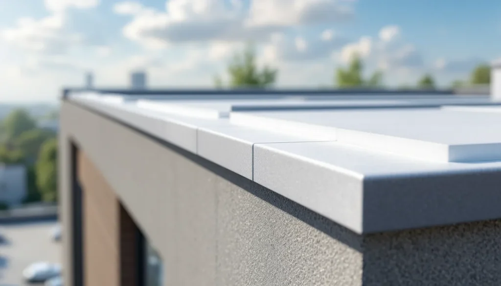
The parapet wall flashing detail is where 80 percent of flat roof leaks actually start. The detail has three components stacked together: continuous base flashing that runs from the roof field up the parapet wall to a termination height of at least 8 inches above the membrane, counter flashing that overlaps the base flashing top edge and embeds into a reglet cut into the wall or masonry, and a coping cap with a continuous cleat that caps the top of the parapet and sheds water back to the roof side. Skip any one of those three and the parapet leaks within 3 to 8 years, regardless of what membrane you used in the field. Petersen PAC-CLAD, Berridge, Englert AmeriClad, and Drexel Metals are the leading coping cap manufacturers; the base flashing material is the same as the field membrane (TPO, EPDM, PVC, or mod-bit).
Last reviewed: August 2026.
The short version
- Three components: base flashing up the wall, counter flashing over the base flashing top edge, coping cap over the wall top.
- Base flashing minimum 8 inches above roof membrane per NRCA. Most manufacturers recommend 10 to 12 inches.
- Counter flashing embeds into a reglet (a horizontal saw cut in masonry, or a surface-mounted reglet on stud walls), sealed with butyl or non-curing mastic.
- Coping cap from Petersen PAC-CLAD, Berridge, Englert AmeriClad, Drexel Metals, or fabricated. Continuous cleat hold-down, 24-gauge minimum, Kynar 500 PVDF paint finish for 30-plus year life.
- Backslope the coping cap toward the roof side (1/4 to 1/2 inch). Water that wants to fall off the wall face instead of the roof face will find every joint and stain the building.
- Termination bar plus sealant alone is not sufficient. Counter flashing OR a proper reglet embedment is required for code and best practice.
Short answer: what the parapet detail does
A parapet wall is a continuation of the building’s exterior wall that rises above the roof level. It defines the roof edge, hides rooftop equipment, supports rooftop railings, and (in the case of fire walls) provides code-required fire separation. The roof membrane has to terminate against this wall, and that termination is the critical waterproofing detail.
Water hits the parapet in three ways. Wind-driven rain across the wall face. Snow piling against the wall. Roof drainage backing up to the parapet if the slope is wrong or drains clog. All three modes try to find their way behind the membrane termination and into the wall cavity. The parapet detail exists to block all three.
The detail is described in detail in the NRCA Roofing Manual, in the SMACNA Architectural Sheet Metal Manual, and in every major manufacturer’s flashing standards (Carlisle, GAF EverGuard, Versico, Sika Sarnafil, Firestone/Holcim, Mule-Hide, Johns Manville). The geometries vary slightly across systems but the principles are identical.
Component 1: base flashing
Base flashing is membrane material that runs from the roof field up the parapet wall, sealed to the field membrane at the bottom and terminated at the top against the wall. The base flashing must be the same material as the field membrane (TPO base flashing on a TPO roof, EPDM base flashing on an EPDM roof, etc.) so that the field-to-flashing seam can be welded, taped, or torched continuously.
The detail:
Height above roof field. NRCA recommends minimum 8 inches above the roof surface. Most single-ply manufacturers recommend 10 to 12 inches as the field standard. Higher termination handles deeper snow load and more wind-driven rain.
Bond to field membrane. The base flashing seam to the field membrane is heat-welded on TPO and PVC, seam-taped and primed on EPDM, torched on modified bitumen. The seam runs continuously around the perimeter and is the highest-stress seam on the entire roof. Failed field-to-flashing seams are the most common parapet leak.
Fasteners. The base flashing is mechanically fastened at the top edge with a termination bar (1/8 by 1 inch aluminum or stainless bar with fasteners every 8 to 12 inches), then the top edge is covered by counter flashing. Some systems use a cant strip at the wall-roof intersection to reduce the bend radius on the base flashing.
Cant strip (optional but recommended). A wood or insulation cant strip at 45 degrees between the deck and the parapet wall reduces the sharp 90-degree bend in the base flashing. Mod-bit roofs almost always require a cant strip. Single-ply roofs benefit from one but do not strictly require it.
Component 2: counter flashing
Counter flashing is metal or vinyl flashing that overlaps the top edge of the base flashing and embeds into the wall above it. The counter flashing has to come from the wall outward and down over the base flashing top edge by at least 4 inches, so that any water running down the wall face cannot get behind the base flashing.
Counter flashing attachment options:
Reglet-embedded counter flashing (best). A horizontal slot (called a reglet) is cut into masonry, stone, or stucco wall 6 to 12 inches above the base flashing top edge. The counter flashing has a folded top edge that inserts into the reglet, locked in with lead wedges or sealant. This is the most weather-tight detail because the counter flashing is mechanically captured in the wall.
Surface-mounted reglet on stud walls. Where reglet cutting is not possible (stud wall with siding, EIFS, etc.), a surface-mounted reglet (also called a snap-lock counter flashing receiver) is fastened to the wall sheathing under the siding. The siding then comes down over the receiver, hiding the fasteners.
Through-wall counter flashing. The counter flashing pierces the wall, sealed on the inside, and folds out over the base flashing on the outside. Used on cavity wall construction where the through-wall path is part of the original design.
Cap nailing alone (counter flashing nailed flat against the wall with fasteners and a bead of sealant) is the bottom-tier detail. It works for the first 5 to 10 years until the sealant fails, then water gets behind. Code in most jurisdictions specifically calls out reglet embedment or surface-mounted reglet as the standard, not face nailing.
For the full counter flashing playbook including reglet cutting and reuse, see counter flashing.
The same wall-junction logic governs sloped-roof details. A sloped roof meeting a vertical wall uses step flashing installation, and a chimney combines step flashing, counter flashing, and a cricket in a related four-part chimney flashing system.
Component 3: coping cap
The coping cap is the metal cap that sits on top of the parapet wall, capping the top course of masonry or the top of the framed wall. The coping protects the top of the wall from water entry and routes water back down to the roof side rather than the building face side.
The detail:
Material and gauge. 24-gauge minimum painted galvanized or aluminum is the commercial default. 22-gauge stainless or copper is the premium spec. Petersen PAC-CLAD, Berridge, Englert AmeriClad, and Drexel Metals all manufacture pre-formed coping in 4 to 12 foot lengths, with corner pieces and end caps available. Field-formed coping from any sheet metal shop is also common, especially for non-standard parapet widths.
Paint finish. Kynar 500 (PVDF) is the gold standard for life and color retention. 30-plus year paint warranty. Hylar 5000 is the second-tier coating. SMP (silicone modified polyester) is the cheap option, 15 to 20 year paint life. Always specify Kynar 500 or PVDF on commercial work.
Backslope. The coping cap must slope to the roof side, not the wall face side. NRCA recommends 1/4 inch per foot minimum. Most installers slope 1/2 inch per foot. The backslope routes water back to the roof, which is set up to handle it. Sloping the coping toward the wall face dumps water down the building face, staining masonry and finding every joint in the coping seams.
Continuous cleat hold-down. A continuous metal cleat (16-gauge galvanized or stainless) fastens to the inside face of the parapet wall (the roof side), and the coping cap’s roof-side leg hooks under the cleat. This holds the coping down against wind uplift without requiring exposed fasteners through the top of the cap. Cleated coping is the manufacturer standard for FM Global wind uplift compliance.
Joint detail. Coping sections meet at flat-lap joints with a slip-sheet (4-inch metal slip behind the joint), sealed with butyl tape. The slip absorbs thermal movement (coping caps expand and contract more than any other roof element). Joints every 8 to 10 feet are normal.
Drip edge. The wall-face leg of the coping cap projects 3/4 to 1 inch beyond the wall face and has a hemmed drip edge. The drip edge breaks surface tension so water falls clear of the wall instead of running back under the coping.
Coping cap brands and what to specify
Petersen PAC-CLAD, Berridge, Englert AmeriClad, Drexel Metals, and ATAS are the leading pre-formed coping manufacturers, all offering 22 or 24-gauge steel and aluminum with a Kynar 500 paint finish. Specify a snap-on or snap-lock profile with a continuous cleat and a 30-plus year paint warranty. Field-fabricated coping is acceptable for residential and small commercial roofs where parapet widths are non-standard.
| Brand | Profile | Material | Paint | Notes |
|---|---|---|---|---|
| Petersen PAC-CLAD | Snap-on coping with continuous cleat | 22 or 24-gauge steel, aluminum | Kynar 500 | Industry leader for commercial coping. 30-plus year paint warranty. |
| Berridge | Custom-formed coping | 22 or 24-gauge steel, aluminum, copper | Kynar 500 | Custom-fab specialist. Good for non-standard parapet widths. |
| Englert AmeriClad | Pre-formed coping with continuous cleat | 24-gauge steel, aluminum | Kynar 500 | Wide color range. Strong residential and small commercial position. |
| Drexel Metals | Drexel Coping system | 24-gauge steel, aluminum | Kynar 500 | Snap-lock system with concealed fasteners. FM Global tested. |
| ATAS | Coping series | 22 or 24-gauge steel, aluminum, zinc | Kynar 500 | Premium positioning. Used on architectural specifications. |
| Field-fabricated | Site-fabricated | 24-gauge steel, aluminum | Kynar 500 sheet stock | Lower cost. Quality depends on shop. Acceptable for residential and small commercial. |
The detail in cross-section: how the three components stack
The three components stack from the roof deck upward: field membrane, an optional cant strip, base flashing run 8 to 12 inches up the wall, a termination bar, counter flashing lapping over the base flashing top edge into a reglet, wall cladding, a continuous cleat, and the coping cap with its backslope and hemmed drip edge. Each layer sheds water onto the one below it.
Imagine a cross-section through the parapet from the roof side. From the bottom up:
1. Roof deck (steel, wood, or concrete) with insulation and field membrane installed on top.
2. Cant strip at the wall-deck intersection (optional but recommended), running the length of the parapet.
3. Base flashing membrane, same material as field membrane, welded or taped to the field at the bottom, running up the wall face to 8 to 12 inches above the field membrane.
4. Termination bar across the top of the base flashing, fastened to the wall at 8 to 12 inch spacing, with sealant behind it.
5. Counter flashing extending down over the termination bar and base flashing top edge, embedded into a reglet in the wall above (or attached to a surface-mounted reglet receiver on stud walls).
6. Wall cladding (brick, stone, EIFS, siding) continuing up to the coping cap.
7. Continuous cleat fastened to the roof-side face of the parapet wall.
8. Coping cap snapping over the wall top and engaging the cleat, with a backslope toward the roof, a hemmed drip edge on the wall face, and lap joints every 8 to 10 feet.
That stack is the detail that lasts 30-plus years. Skip the cant strip and you can still get to 25. Skip the counter flashing and rely on termination bar plus sealant and you are looking at 8 to 12 years before the sealant fails and water finds its way in.
Where the detail fails: install errors we see over and over
Most parapet failures trace to six install errors: base flashing run too short, no counter flashing behind the termination bar, coping sloped toward the wall face, coping joints built without slip-sheets, face-fastened coping, and a counter flashing reglet cut too low. Each defect lets water past a component that was supposed to block it, and each has a defined repair with its own flat roof repair cost.
Base flashing too short. Installer runs the base flashing 4 to 6 inches up the wall instead of 8 to 12. Snow piles or wind-driven rain run over the top edge. Repair is rip out, run new base flashing to proper height, reseal field seam.
No counter flashing, just termination bar plus sealant. The sealant fails at year 5 to 8. Water gets behind. Repair is cut a reglet (or install a surface-mounted reglet receiver), install proper counter flashing.
Coping sloped the wrong direction. Coping slopes toward the wall face instead of the roof. Water stains the building face, finds every coping joint. Repair is remove coping, re-shim or re-fabricate with correct slope, reinstall.
Coping joints without slip-sheets. Coping sections butted together with sealant only. Thermal movement (coping caps expand and contract 1/2 inch over 10 feet seasonally) breaks the seal. Slip-sheet behind the joint absorbs the movement and prevents the failure.
Face-fastened coping. Coping cap fastened through the top with exposed screws and washers. Each fastener is a future leak. FM Global will not approve a face-fastened coping for wind uplift compliance. Continuous cleat is the standard.
Counter flashing reglet too low. Reglet cut at the same level as the base flashing top edge instead of 6 to 12 inches above. No overlap. Water runs straight in. Repair is cut a new higher reglet.
For the broader leak diagnostic path see roof flashing and roof flashing repair.
Height requirements: code and manufacturer minimums
Minimum base flashing height above the roof runs 8 inches per the NRCA Roofing Manual, with single-ply manufacturers such as Carlisle and Sika Sarnafil calling for 10 inches on their systems. In snow climates the NRCA recommendation rises to 12 to 16 inches. The table below lists the published minimum for each major reference and membrane manufacturer.
| Reference | Minimum base flashing height above roof |
|---|---|
| NRCA Roofing Manual | 8 inches |
| Carlisle Sure-Weld TPO | 10 inches |
| GAF EverGuard TPO | 8 inches |
| Firestone/Holcim RubberGard EPDM | 8 inches |
| Sika Sarnafil PVC | 10 inches |
| Versico VersiWeld TPO | 8 inches |
| Johns Manville | 8 inches |
| Mule-Hide | 8 inches |
| NRCA snow climate recommendation | 12 to 16 inches |
If you are in a snow climate (any region with sustained snow cover over 6 inches), go to the higher end of the recommendation. Snow drifts pile against parapets and a 12-inch base flashing is the minimum that handles drift conditions.
Coping width and overhang
The coping cap has to be wider than the wall so it drips clear of both faces, typically 1 inch of overhang on each side. An 8-inch single-wythe wall takes a 10-inch cap; a 12-inch double-wythe wall takes a 14-inch cap. Both overhangs have to be hemmed for stiffness and drip-edge function. The table gives standard coping widths by wall thickness.
| Wall width | Coping width (typical) | Overhang each side |
|---|---|---|
| 8 inch (single wythe) | 10 inches | 1 inch each side |
| 10 inch | 12 inches | 1 inch each side |
| 12 inch (double wythe) | 14 inches | 1 inch each side |
| 16 inch | 18 inches | 1 inch each side |
| 24 inch (low parapet on commercial) | 26 inches | 1 inch each side |
The overhang has to be hemmed for stiffness and drip-edge function. A flat-edge overhang (no hem) sags over time and the drip-edge function fails.
Fire-wall parapets: extra detail required
A fire-wall parapet has additional requirements beyond standard weatherproofing. The wall must be continuous through the roof assembly with a fire-rated construction (typically 2 hours), and the parapet must extend at least 30 inches above the roof in most code jurisdictions (sometimes higher).
For fire-wall parapets:
The base flashing has to extend higher to match the fire wall height. 30-inch parapet means 30 inches of base flashing up the wall.
Penetrations through the fire wall (HVAC ducts, electrical conduits) require fire-rated sealants and through-penetration firestop systems (e.g., 3M FireBlock, STI Specified Technologies). These are separate from the roof waterproofing detail but interact with it.
Counter flashing and coping cap detail is the same as a standard parapet, but the fire wall requires the inside-of-parapet face to be the same fire-rated material as the wall body, not the standard EIFS or siding.
Existing parapet leaks: diagnostic path
Diagnosing a parapet leak works from the inside out: locate the interior wet area, project it to the corresponding parapet exterior, then inspect the coping cap, counter flashing, and base flashing in turn before running a controlled water test. Working the components from the top down isolates which of the three has failed and where the water is entering.
If a parapet is leaking, the diagnostic path:
Step 1: Identify the wet area inside. Note the location of interior staining or water entry. Project that location to the corresponding parapet exterior.
Step 2: Inspect the coping cap. Walk the coping looking for failed joints, missing cleats, face-fasteners, sealant degradation. Coping failures show up as water staining on the wall face below the coping joint.
Step 3: Inspect counter flashing. Check whether counter flashing is present at all, whether the reglet seal is intact, whether the counter flashing has pulled away from the wall, and whether sealant at the reglet has degraded.
Step 4: Inspect base flashing. Check the base flashing height above the roof, the seam to the field membrane, and the termination bar at the top. Probe the base flashing seam with a smooth dull tool to check for separation.
Step 5: Water test. Run a garden hose at the parapet exterior, starting at the coping and working down. Have an observer inside watching for water entry. Note the location and time. This isolates the leak path.
For the full leak repair flow, see roof leak repair and how to fix a roof leak.
Parapet wall roofing: frequently asked questions
How high should parapet base flashing run above the roof?
The NRCA Roofing Manual sets an 8-inch minimum above the roof membrane, while most single-ply manufacturers such as Carlisle and Sika Sarnafil recommend 10 to 12 inches. In snow climates with sustained cover over 6 inches, run the base flashing 12 to 16 inches so it clears the drifts that pile against the wall. Higher termination also handles more wind-driven rain.
Do I need counter flashing if I already have a termination bar and sealant?
Yes. A termination bar plus sealant alone lasts only 5 to 10 years before the sealant fails and water gets behind the base flashing. Counter flashing embedded in a reglet, or a surface-mounted reglet receiver on stud walls, is required for code and best practice in most jurisdictions. Face nailing is the bottom-tier detail and does not meet the standard.
Which way should a coping cap slope?
A coping cap must slope toward the roof side, never the wall face. NRCA recommends 1/4 inch per foot minimum, and most installers use 1/2 inch per foot. The backslope routes water onto the roof, which is built to handle it. Sloping toward the wall face dumps water down the building, stains the masonry, and finds every joint in the coping seams.
What holds a coping cap down against wind?
A continuous metal cleat, 16-gauge galvanized or stainless, fastens to the roof-side face of the parapet, and the coping’s roof-side leg hooks under it. This resists wind uplift without exposed fasteners through the top of the cap. Cleated coping is the manufacturer standard for FM Global wind uplift compliance; a face-fastened coping will not pass.
How long does a properly built parapet detail last?
A full detail with base flashing, counter flashing, and a cleated coping cap lasts 30-plus years. Skip the cant strip and you can still reach 25. Rely on a termination bar plus sealant with no counter flashing and you are looking at 8 to 12 years before the sealant fails and water finds its way behind the membrane.
What material should parapet base flashing be?
Base flashing must match the field membrane so the seam can be joined continuously: TPO base flashing on a TPO roof, EPDM on EPDM, PVC on PVC, and torched mod-bit on modified bitumen. That field-to-flashing seam runs around the whole perimeter, carries the highest stress on the roof, and is the most common source of parapet leaks.